Hardware
Specifications
Power |
PH2.0 2P, 3.3V-6V, Min 3.55V@600mA |
USB |
USB 2.0 Type-C, PD 5V |
MCU |
ESP32 S3 |
Flash |
8MB |
PSRAM |
2MB |
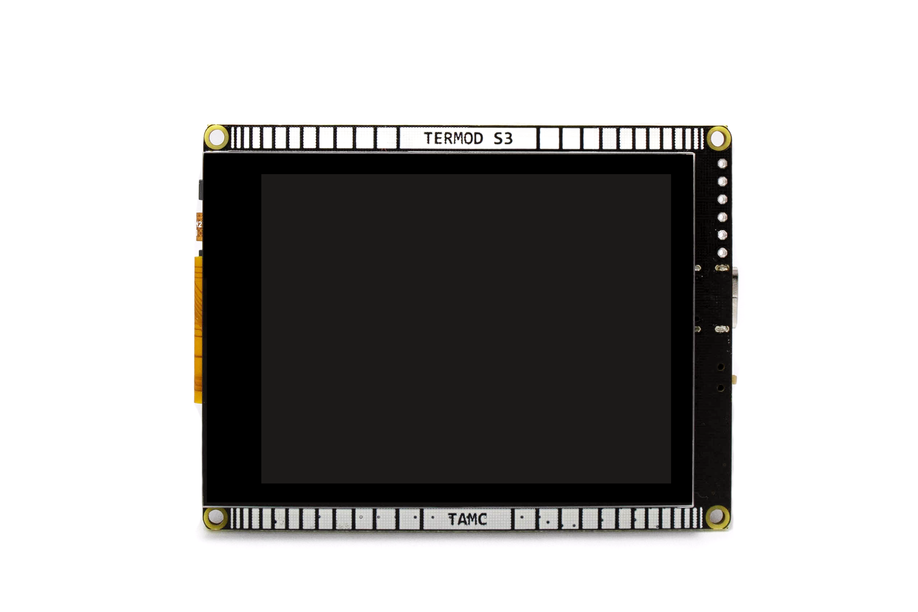
Display |
2.8 Inch 320x240 IPS, SPI |
Touch |
FT6206 Capacitive IIC |
Size |
76x58mm |
Mounting Holes |
M2 x 4 |
SD Card |
Micro SD with SPI Interface |
Buttons |
IO0 and Reset button |
Pinout
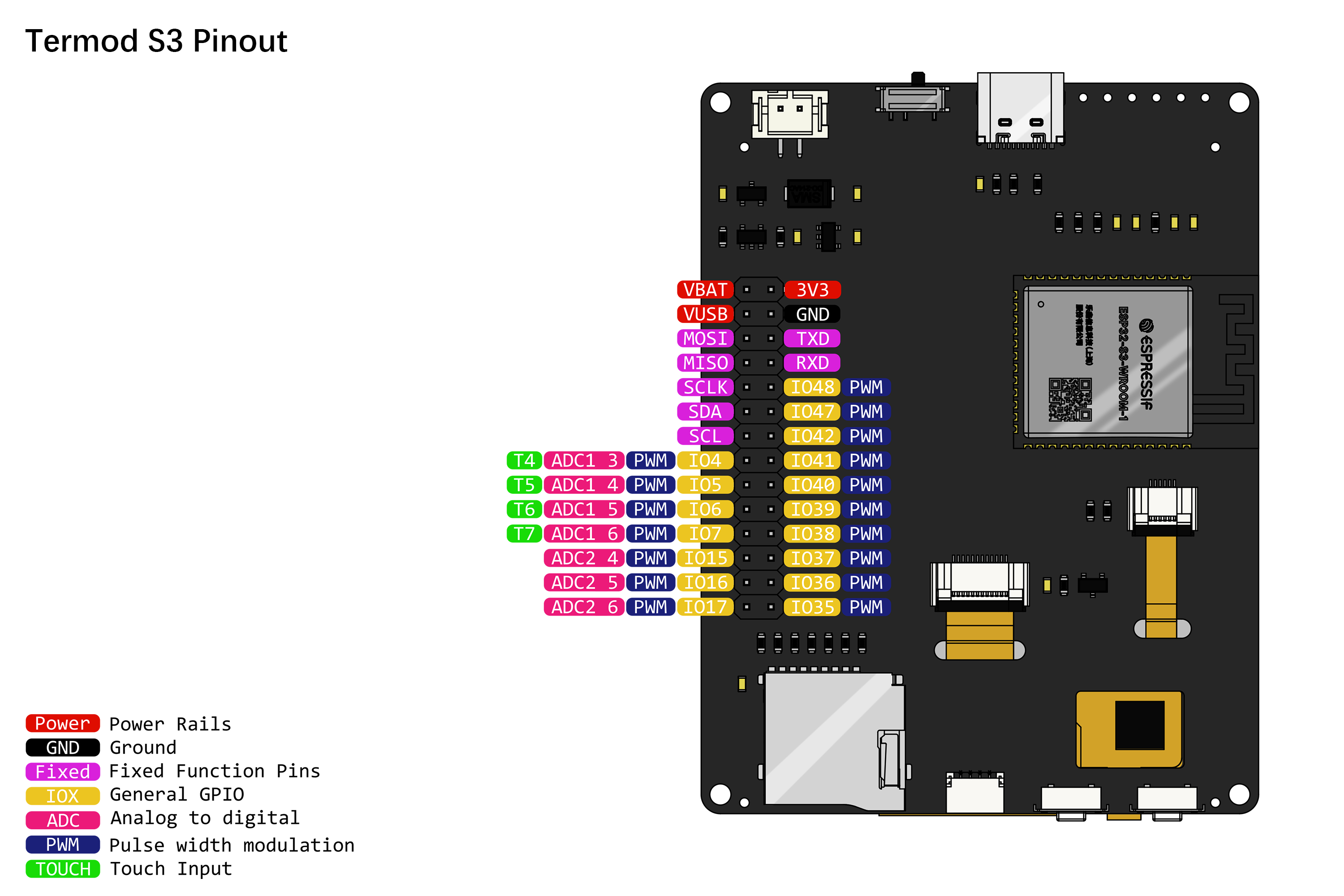
Pin Assignment
General Pins
ESP32 S3 |
General |
|---|---|
GPIO11 |
MOSI |
GPIO13 |
MISO |
GPIO12 |
SCLK |
GPIO8 |
SDA |
GPIO9 |
SCL |
GPIO1 |
Battery Level |
GPIO2 |
Charge Detect |
GPIO0 |
Button |
GPIO10 |
TFT CS |
GPIO18 |
TFT D/C |
GPIO14 |
TFT Reset |
GPIO48 |
TFT Backlight (See Selectable pins) |
GPIO21 |
uSD CS |
GPIO47 |
uSD Card Detect (See Selectable pins) |
LCD Pins
ESP32 S3 |
LCD |
|---|---|
GPIO11 |
MOSI |
GPIO13 |
MISO |
GPIO12 |
SCLK |
GPIO10 |
CS |
GPIO18 |
D/C |
GPIO14 |
Reset |
GPIO48 |
Backlight (See Selectable pins) |
FT6206 Touch Screeen Pins
ESP32 S3 |
FT6206 |
|---|---|
GPIO8 |
SDA |
GPIO9 |
SCL |
NC |
INT |
NC |
RST |
Micro SD Card Pins
ESP32 S3 |
Micro SD Card |
|---|---|
GPIO11 |
MOSI |
GPIO13 |
MISO |
GPIO12 |
SCLK |
GPIO21 |
CS |
GPIO47 |
Card Detect (See Selectable pins) |
Selectable pins
JP1 and JP2 are solder pads for selecting functions.
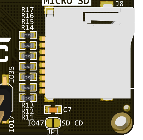
JP1 is for selecting the micro SD card detect pin. If you need to detect inserting a card, you can solder JP1 together, and reads IO47 for card detecting. IO47 will be pulled LOW when a card is inserted.
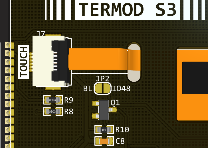
JP2 is for selecting the TFT backlight pin. If you need to control the backlight, you can solder JP2 together, and controls IO48 for backlight control. Set IO48 HIGH to turn on backlight.
Schematic
Power management
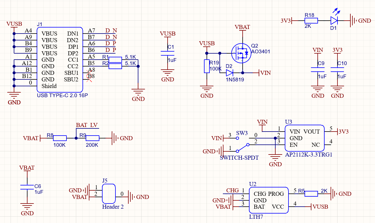
Power includes 2 inputs: 5V USB Type C and battery, joined together with a simple power selector, which cuts of the batteries when USB is pluged in.
A 3.3V power indicator LED D1 to indicate the power status.
A 100K/200K voltage divider divide the battery voltage to IO1 BAT.
LTC4054 Lithium-ion battery charger.
Charge signal is connected to IO2 CHG. LOW as charging.
ESP32 S3
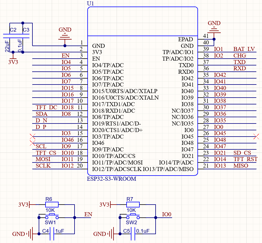
Simple setup for ESP32 S3 with buttons(IO0 and EN).
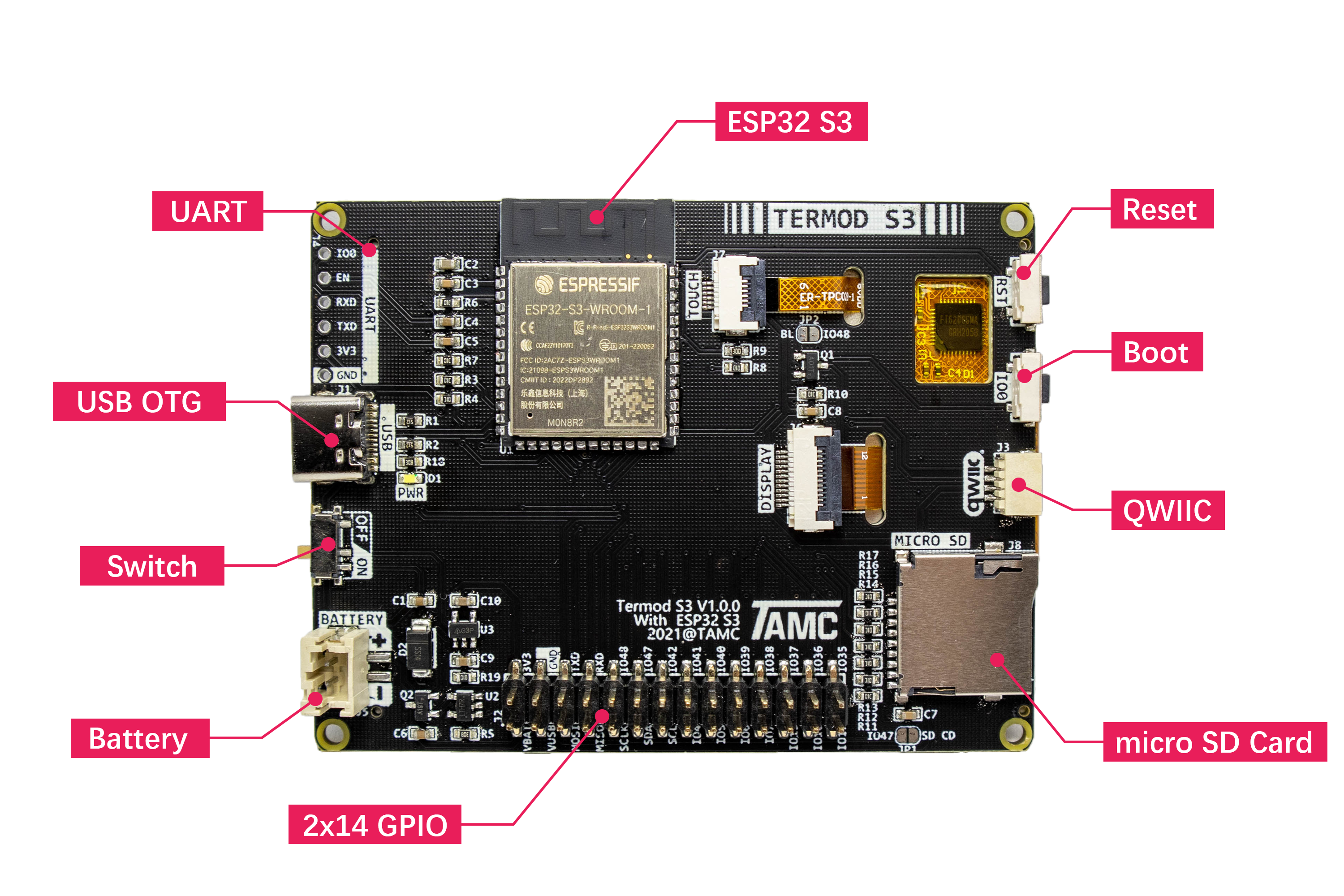
Connectors
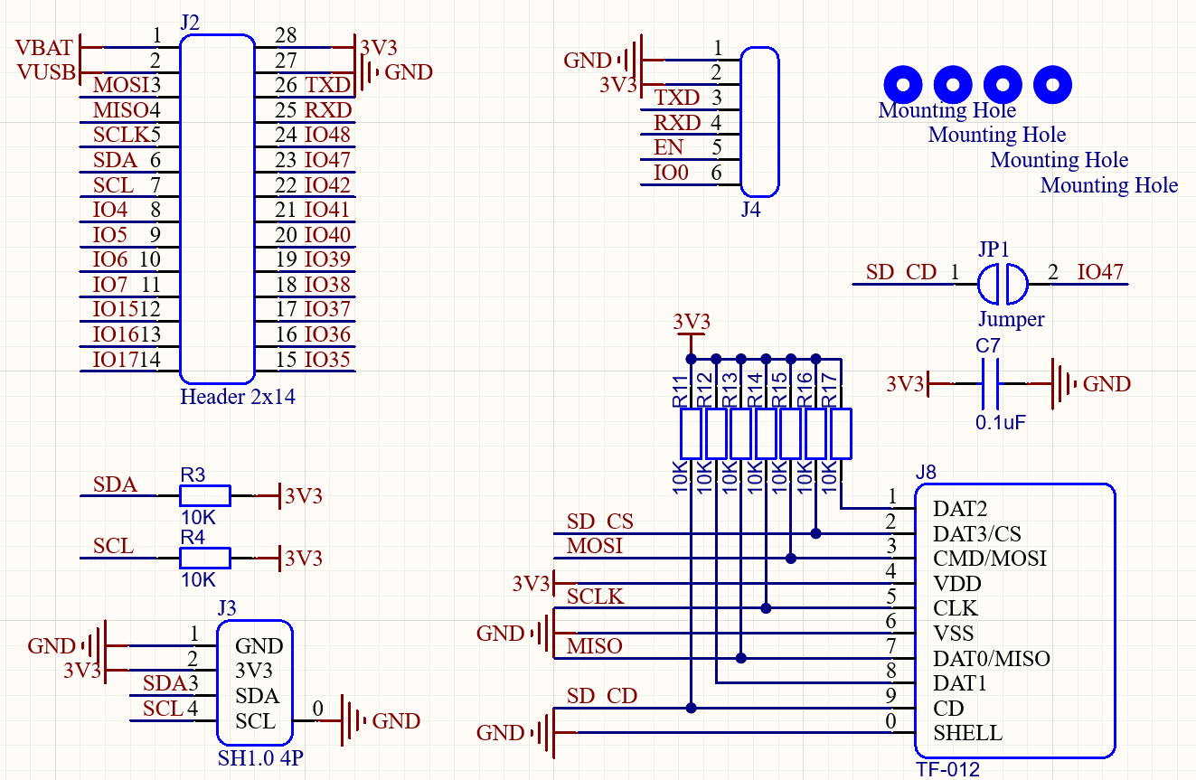
J2: GPIO breakout connector: pin header 2x14 2.54mm.
J3: I2C SH-1.0-4P connector compatible with Qwiic and STEMMA QT
J4: Serial connector with
IO0andENfor easy programming.J8: Micro SD Card connector.
Display & Touch Panel
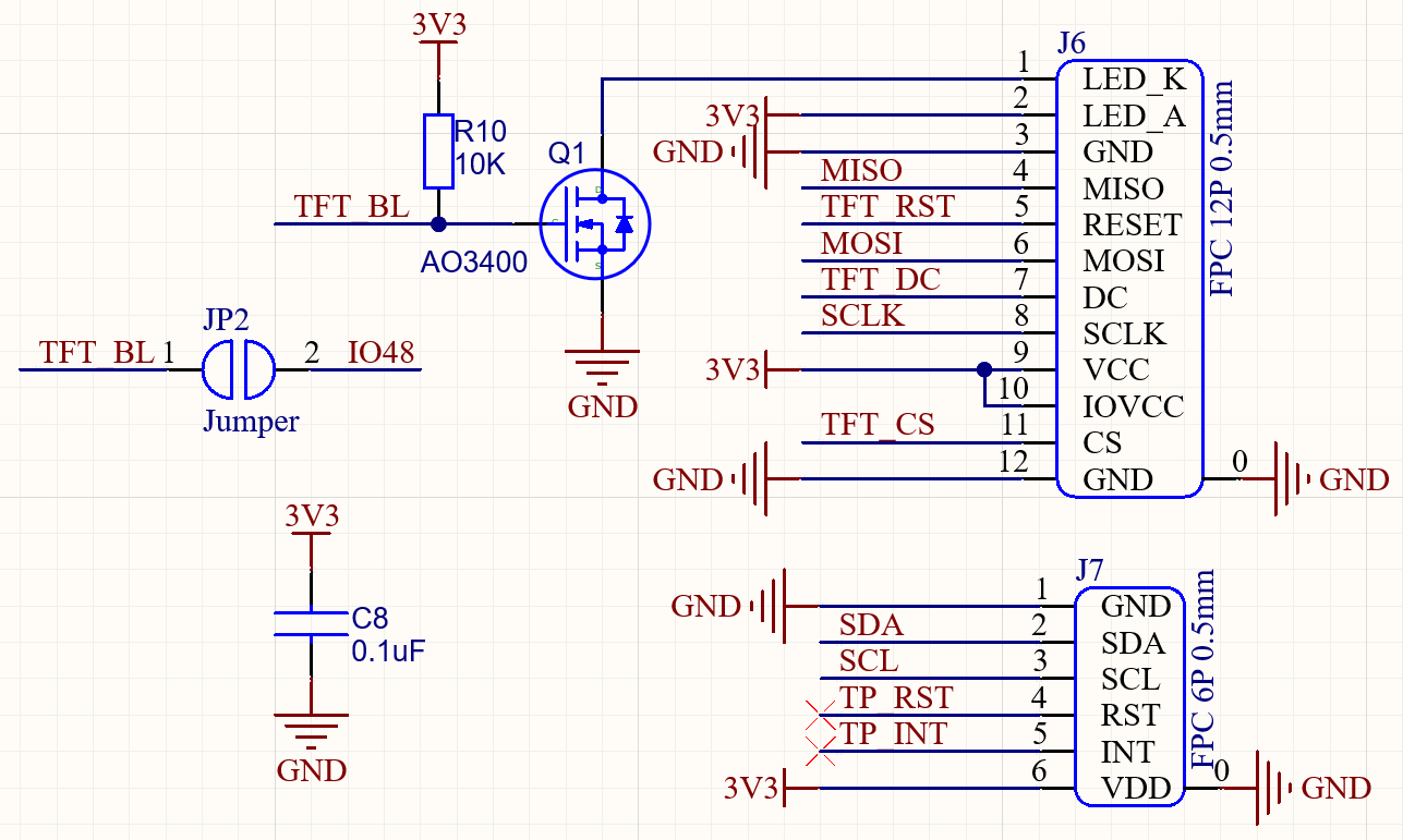
J6: ST7789V display with SPI interface.
J7: FT6206 touch panel with I2C interface.
NMOS
Q1to control the backlight.
Mechanics
Drawing DXF:
termod-s3-v1.0.0-mechanical-drawing.dxfDrawing PDF:
termod-s3-v1.0.0-mechanical-drawing.pdf3D Model:
termod-s3-v1.0.0-3d.step